How to Perform IMU Yaw Correction Static Calibration
Posted on December 10, 2025 by Zach Strout

While we did a blog post a couple months ago about all of the different types of calibrations, it was more of an overview rather than a detailed description about it how to implement it. With the release of the One Leg Flexion app, we wanted to dive in deep on how the static calibration works for it. We hope that this post will help researchers when implementing static calibration for their own research.
The main goal of the static calibration is the combination of two things: we want to make sure all of the IMUs have the same world frame of reference, and we want to align them within that frame of reference to the correct body segments. The most important thing is not that they have some sort of global frame of reference, such as ENU (East, North, Up), but that they share a reference frame. After they share a reference frame, we then can align that reference frame to the body segments. So static calibration is actually two, independent things, so we will split up this static calibration topic into two different posts: yaw correction and body-to-segment calibration.
Yaw Correction
Yaw Correction
Like we discussed in our Euler Angle blog post, orientation can be broken down into three components: yaw, pitch and roll. The static calibration starts with the yaw correction. Pitch and roll typically do not need correction since the accelerometer provides a good reference to what is "down". As long as the IMU is stationary, nothing can really influence or bias this “down“ direction significantly. Yaw is another case though. If the IMU has a magnetometer, the absolute yaw reference will be North. There might be slight bias in that direction though due to magnetic things around the IMUs. This is especially a problem since the earth’s magnetic field is actually pretty weak compared to other magnetic things around like refrigerator magnets that are typically around 100x stronger. If there is not a magnetometer in the IMU or if it is not used, then usually the starting yaw is taken as "zero". The calculated yaw is the angular distance from the starting yaw orientation and not any specific external reference. This means that unless you are extremely careful to make sure that all of the IMUs have the same initial orientation when powered on, all of the IMUs will have different headings and certain joint angle calculations will be wrong. These different headings need to be calibrated so that they all share one common heading. This can be done by understanding how the IMUs are placed on the body segments.
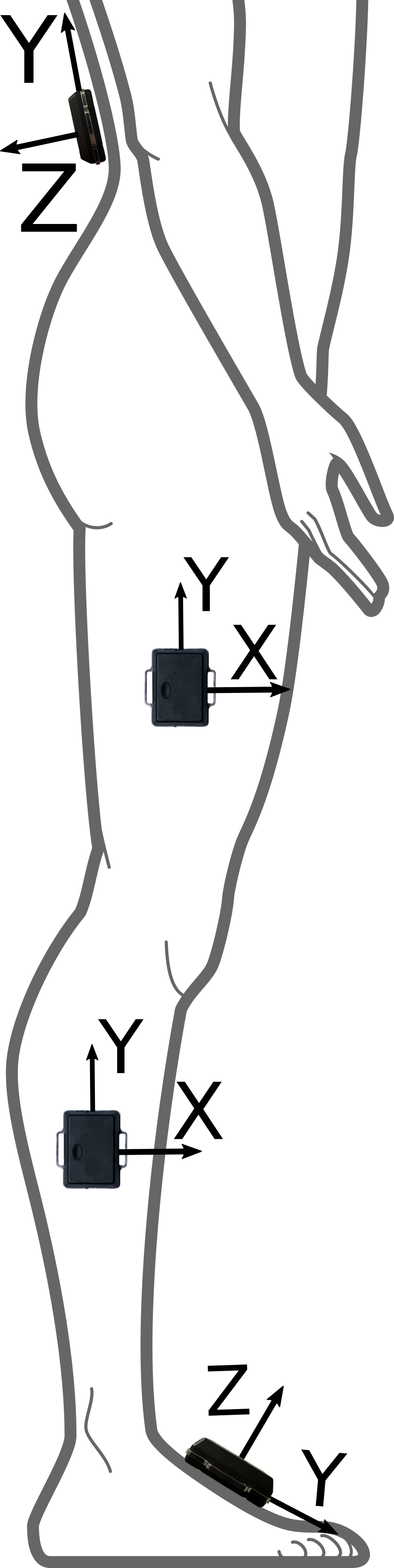
IMUs for One Leg Flex app (right leg)
In the case of our Leg Flexion App, the IMUs are placed along the lateral side of either the left or right leg with the y axis pointed vertically and z axis lateral, the dorsal surface of the foot with the y axis pointed anteriorly, and the posterior surface of the pelvis with the y axis pointed vertically, so we can use these known theoretical orientations to calculate the yaw offsets used to compensate for the yaw error. Whether these yaw offsets are negative is determined by the right hand rule which says that the direction that the fingers curl on the right hand is positive. The right hand rule also governs the unlabeled axes in the diagram.
First, we will need to pick a main yaw reference which is one of the IMUs. While it can be arbitrary, we use the pelvis as the main yaw reference since it is the root of motion and closer to the center of mass. We can define the initial yaw of the pelvis to be zero. The shank and thigh yaw offsets depend on what leg has the IMUs. If the flexion is being measured in the right leg, the right hand rule says that the yaw offset will be -90 for the shank and thigh. This -90 degrees is the amount of yaw that it would take to align the thigh or shank IMUs with the pelvis IMU. Likewise, the yaw offset for the left shank or thigh will be 90 degrees. The foot IMU is a little tricky. What we need to do first is to rotate it so that the positive y axis is pointed vertically like the other nodes. Now, we can see that it is actually in the same orientation as the pelvis, so there is no yaw offset for this IMU.
Python allows us to finally do this calculation by using a fantastic rotation library in Scipy. This library allows us to transform from any rotation format (rotation matrix, euler angles, quaternions, or axis-angle) to a neutral format then to any other format. The neutral format, a Rotation object which we shorten to `R`, allows us to use typical operations when thinking of rotation matrices like multiplication to chain rotations or inversion to reverse a rotation. So, we can do $R_{A \to B} \times R_{B \to C} = R_{A \to C}$ by literally multiplying the different Rotation objects in Python. So we can first start the yaw correction by doing the following:
quat_base = [data[base_imu][f"Quat{i + 1}"] for i in range(4)]
R_quat_base = R.from_quat(quat_base, scalar_first=True)
base_yaw, _, _ = R_quat_base.as_euler("ZYX", degrees=True)
base_yaw = (base_yaw + 180) % 360 - 180
This creates a Python list, which is kind of like an array, of the base IMU's quaternion values using list comprehensions, create a Rotation object using the R.from_quat method, convert that Rotation object to intrinsic or body euler angles in the ZYX order, extract the yaw component of the euler angles, and make sure that the angle is between -180 and +180 degrees. The last line helps compensate and regulate the addition of yaw angles. For example, if one yaw angle was +179 degrees and another yaw angle was -179 degrees, the yaw error between them would look like -358 which looks like almost a full turn instead of the 2 degrees that it is truly different. It does this normalization by adding 180, finding the remainder after dividing by 360, then subtracting 180. So if the angle is 20 degrees, the result after adding 180 would be 200, the remainder after dividing by 360 would be 200, and this minus 180 would be 20. If we pick a larger number like 200, adding 180 gives 380, the remainder after dividing by 360 is 20, and this minus 180 is -160. If we add 360 degrees to this, we can see that -160 and 200 are the same angle, so all of the calcualtions still work out.
The yaw correction also removes the base yaw so that the starting yaw is zero like we assumed above. This is helpful for anatomical reference frames like Opensim's Z-up, X-forward, and Y-left global coordinate system. That is what the next couple lines do:
quat_base = [data[base_imu][f"Quat{i + 1}"] for i in range(4)]
R_quat_base = R.from_quat(quat_base, scalar_first=True)
base_yaw, _, _ = R_quat_base.as_euler("ZYX", degrees=True)
base_yaw = (base_yaw + 180) % 360 - 180
This is just creating a global yaw transform and adding it to the list of transforms. The next section is where the main list of correction transforms is made.
    for sensor_idx, sensor_data in enumerate(data):
        if sensor_idx == base_imu:
            continue
        quat = [sensor_data[f"Quat{i + 1}"] for i in range(4)]
        R_quat = R.from_quat(quat, scalar_first=True)
        yaw, _, _ = R_quat.as_euler("ZYX", degrees=True)
        yaw = (yaw + 180) % 360 - 180

        yaw_error = yaw - base_yaw - starting_yaw_offsets[sensor_idx]
        yaw_error = (yaw_error + 180) % 360 - 180
        print(f"Yaw error for {sensor_idx}: {yaw_error}")

        per_sensor = R.from_euler("Z", -yaw_error, degrees=True)
        # Apply per-sensor correction, then global base de-yaw so base ends up at zero
        self.yaw_transforms[sensor_idx] = self.global_yaw_transform * per_sensor
We only want to perform this work on the non-base sensors, so this skips if the sensor index is the same as the base index. We do the same quaternion extraction, Rotation object creation, and yaw extraction and angle normalization as we do for the base yaw. We then find the yaw error between the current IMU and the base compensating for the starting yaws. If the IMU is normally 90 degrees offset from the base and the difference from the base and the current IMU is 90 degres, that 90 degrees is not error. We do another scaling to make the rest of the math more predictable, and then create a Rotation object for this yaw error. The last step is to chail the global yaw transformation and the individual sensor error together so that one Rotation object for the total rotation can be made. Finally, we have a list of correction transformations that we can use to correct the yaw for new sensor data.
The process of correcting the yaws is more straightforward.
    def correct_yaw(self, data):
            for sensor_idx, sensor in enumerate(data):
                quat = [sensor[f"Quat{i + 1}"] for i in range(4)]
                R_quat = R.from_quat(quat, scalar_first=True)
                corrected_quat = self.yaw_transforms[sensor_idx] * R_quat
                corrected_quat = corrected_quat.as_quat(scalar_first=True)
                for i in range(4):
                    data[sensor_idx][f"Quat{i + 1}"] = corrected_quat[i]
            return data
We can get the data, perform the same quaternion extraction, convert that to the Rotation object, perform the yaw correction to the IMU, then put it back into the data list. One important thing is that could be mentioned is the order of the multiplication for the yaw correction transformation and the IMU's quaternion. Multiplying or chaining together orientations is non-commutative which means that $R_1 \times R_2$ is generally not $R_2 \times R_1$. This means that the order of the multiplication is really important and that one way of multiplying the rotations is wrong for this specific application. This does not apply to rotations in 2 dimensions though. For example, the multiplication that we did above for the global yaw transform and the per-sensor transforms could have been done in the other order with the global yaw transform coming after the per-sensor transform. This is because both were restricted to the "Z" axis. This is not the case for the current IMU quaternions though since they are true 3d rotations. This means that we need to be really careful about what way we multiply, either multiplying the IMU quaternion on the left or the right.
A good way of thinking about this problem is to be more systematic. Lets say that the IMU rotation is a transformation from a global frame to a IMU frame. Another way of writing this would be $R_{G \to S}$ where $R$ is the rotation, $G$ is the global frame, and $S$ is the sensor or IMU frame. Now, the $G$ in this definition is not the true $G$. We know that it needs yaw correction, so lets change the name of it to $G_\text{yaw_err}$. What we really want though is $G$ to be the true global frame, so we need a transformation from $G_\text{yaw_err}$ to $G$. This is what the yaw transformation is. We have these two transformations that we need to chain together. The way that we can think of this chaining though is by travel. Each rotation is sort of like a flight that goes from one destination to another. If you want to get from Berlin, Germany to São Paulo, Brazil you will need to stop somewhere in the middle since there is no direct flight between the two cities. One route would involve a flight from Berlin to Madrid, Spain then from Madrid to São Paulo. Each step of this trip depends on the previous location. So it would not make sense to say you first take the flight from Madrid to São Paulo then you take the flight from Berlin to Madrid. The same goes for the rotations. Rotations really only make sense if you make sure to chain them properly. So if we have the Rotation $R_{G_{\text{yaw_err}}\to S}$ and $R_{G\to G_{\text{yaw_err}}}$, it makes more sense to go from $G \to G_{\text{yaw_err}}$ then $G_{\text{yaw_err}} \to S$ than to go from $G_{\text{yaw_err}} \to S$ then $G \to G_{\text{yaw_err}}$. When the multiplication is performed, it is as if the middle frame, $G_{\text{yaw_err}}$, does not exist so that we finally have $R_{G\to S}$.
Since this is such an important concept, we made a simulation of yaw correction below. On the left is the correct, left multiplication, and on the right is the incorrect, right multiplication. The grey wireframe outline is the uncorrected IMU. The yaw slider adds the yaw error, and the simulation removes it. The pitch and roll sliders allow various different orientations to be tested with the simulation. With this simulation, there are some things that you can try. With the pitch and roll close to zero, you can see that either left or right multiplication is about the same. This is because the rotation is restricted to a plane. Rotation constrained to one plane, which can be thought of as 2d rotation, is commutative, so rotating by multiplying on the left or right is the same. You can also see how significant the yaw error is with various different pitch or roll angles. When the pitch angle is close to 90 degrees, the error is substantial.
To use the yaw correction for an algorithm, you can use the first sample of data to calibrate the yaw correction then just correct the yaw for each sample after that initial sample using the saved calibration quaternions. If the first sample is used for calibration, the subject/patient will just need to be in the right pose for this first sample since the assumed yaw offsets need to be close to the actual yaw offsets. This algorithm is actually the first step towards a functional calibration for yaw. If you are able to have the subject/patient walk for 5-10 meters, extract the acceleration, perform Principal Component Analysis to find the principal components, and find the true yaw offsets. This is what papers such as Robust PCA-based Walking Direction Estimation via Stable Principal Component Pursuit for Pedestrian Dead Reckoning do to get walking direction and the orientation of the sagittal plane.
You can find the full source code for this yaw correction along with some other helper classes in our Core-Algorithms github repo. This repository has a couple gait phase detection algorithms and a class that makes the Scipy rotations library work better for older versions of the library.