How to Perform IMU Static Calibration
Posted on March 07, 2026 by Zach Strout
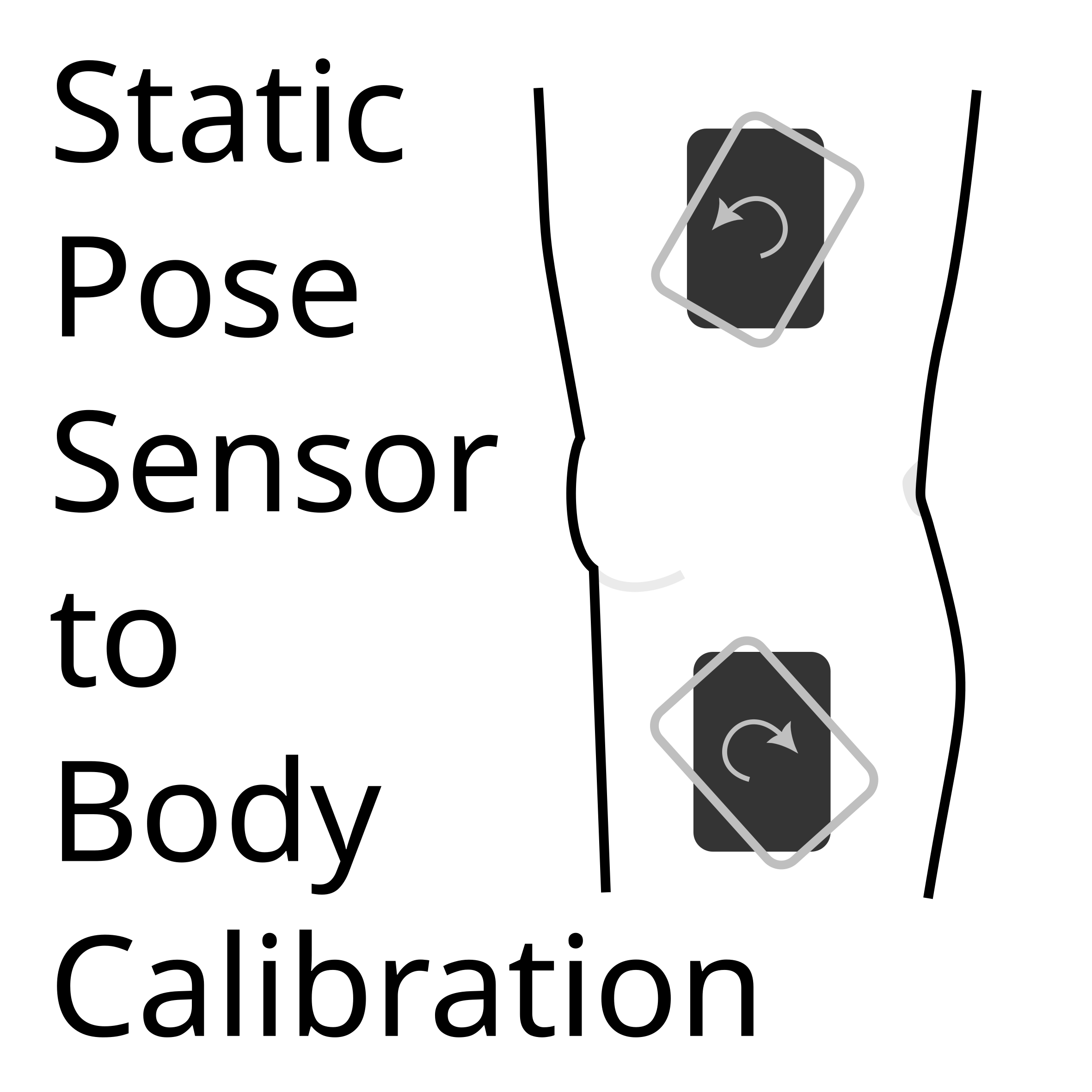
Static pose calibration is one of the most commonly used sensor to segment alignment methods due to its simplicity and consistency. After the yaw for each segment’s IMU has been corrected using a yaw correction method, the subject or patient just needs to stand in a known pose, and the IMUs will be given the correct transformation from their current orientation to the segment orientation. The transformation is defined by the calibration equation. This post will discuss the calibration equation and how to apply it.
Calibration Equation
The main calibration equation is $$ R_{G \to S} \times R_{S\to B} = R_{G \to B} $$where $R_{G \to S}$ is the rotation from the global frame to the sensor frame, $R_{S \to B}$ is the rotation from the sensor frame to the body frame, and $R_{G \to B}$ is the rotation from the global frame to the body frame (see figure on right/below). The way that we can derive this is by knowing that we want $R_{G \to B}$ and have $R_{G \to S}$ which is the actual orientation from the IMU. Going from $R_{G \to S}$ to $R_{G \to B}$ requires a rotation from $S$ to $B$. This rotation would be $R_{S\to B}$, so we can just chain that onto the rotation $R_{G \to S}$.
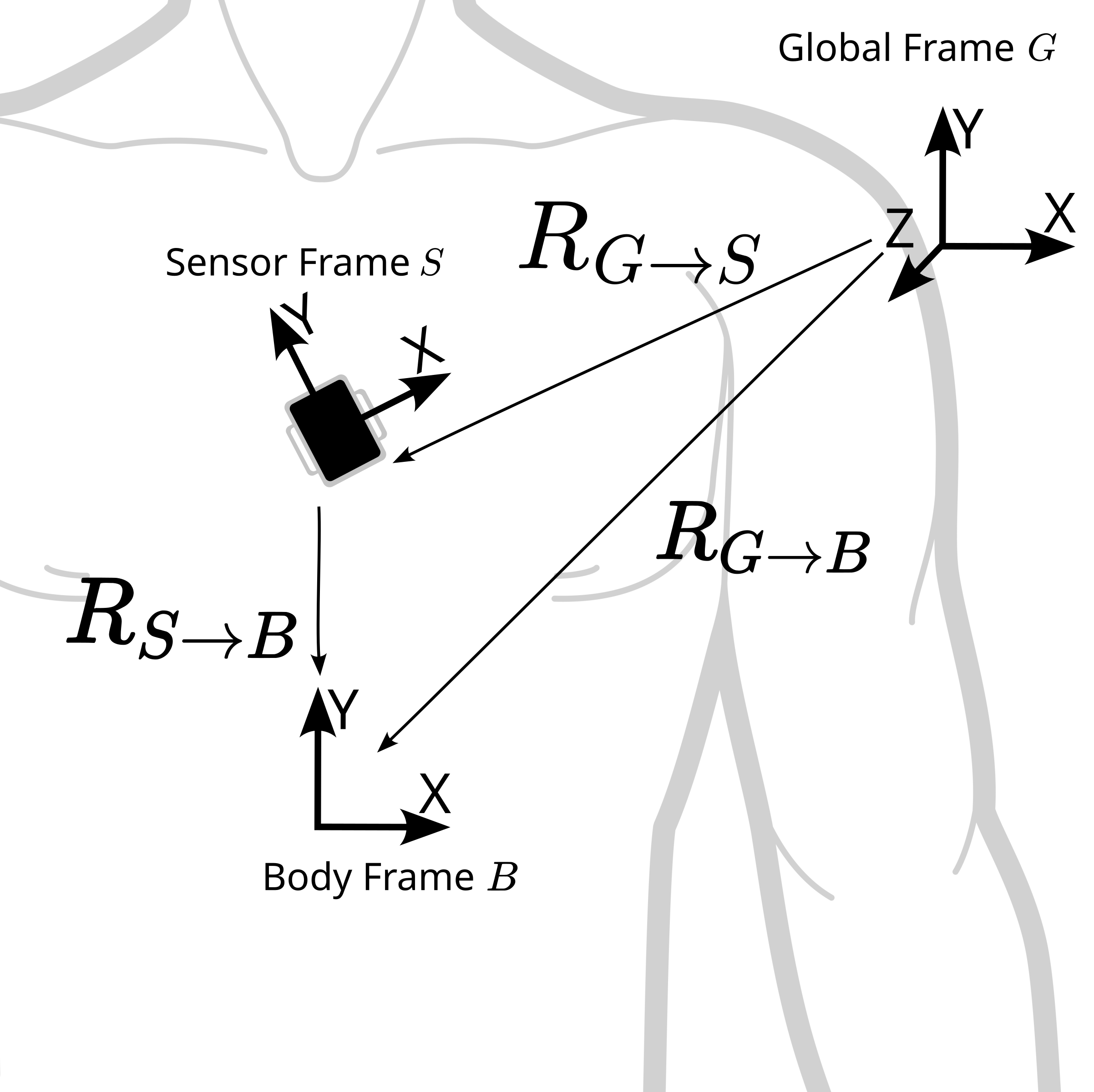
$ R_{G \to S} $ rotates from the global frame to the sensor frame, $ R_{S\to B} $ rotates from the sensor frame to the body frame, and $ R_{G \to B} $ rotates from the global frame to the body frame
Before we move onto the static calibration, lets take a quick detour to understand how manual calibration and static pose calibration differ since each interact with this calibration equation differently. The calibration equation $ R_{G \to S} \times R_{S\to B} = R_{G \to B} $ really has only two unknowns, $R_{S\to B}$ and $R_{G \to B}$. $ R_{G \to S}$ is the actual orientation from the IMU, so this is known in all cases. To resolve this equation, we need to know either $R_{S\to B}$ or $R_{G \to B}$. Static pose calibration and manual calibration do this in opposite ways.
Manual Calibration
How manual calibration resolves one of the unknowns is to manually align the sensor frame with the body frame. This means that it takes no rotation to rotate from the sensor frame to the body frame. Mathematically, you align the IMU so that $R_{S\to B}$ is the null rotation. In matrix terms, this would be the identity matrix, $I$. In euler angles, this would be zero yaw, pitch, and roll. This would effectively define $R_{G \to B}$ as $R_{G \to S}$ since multiplying by the null rotation does nothing. The nice thing about this calibration method is that it is not dependent on knowing $R_{S\to B}$ since it is defined by physically moving the IMU. This is a great calibration method for subjects or patients who can not get into a known calibration pose. The downside is that it requires skill to align the IMU to the right frame. It supposes that it is possible to align the IMU. There might be cases where this is actually not possible. For example, it might be difficult to manually align the IMU on the lateral surface of the thigh so that one of the axes is parallel with the main axis of the femur.
Static Pose Calibration
Static Pose Calibration solves the calibration equation the opposite way. Instead of taking $R_{S\to B}$ as the known, it takes $R_{G \to B}$ as the known. If the body segment can get into some known pose, we can rearrange the the calibration equation to solve for $R_{S\to B}$ and plug in all the known values. Solving it looks like
$$\begin{aligned} R_{G \to S} \times R_{S\to B} &= R_{G \to B} \\ R^{-1}_{G \to S} \times R_{G \to S} \times R_{S\to B} &= R^{-1}_{G \to S} \times R_{G \to B} \\ R_{S\to B} &= R^{-1}_{G \to S} \times R_{G \to B} \end{aligned}$$
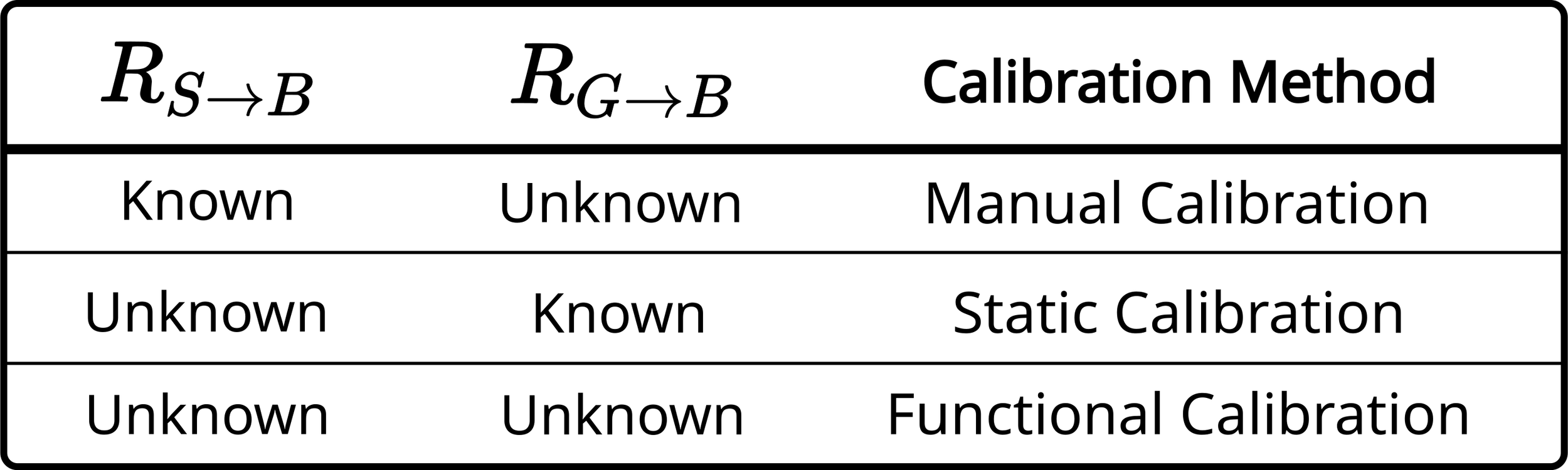
Using static or manual calibration depends on what you know about the orientation of the segments or the IMUs
where $ R^{-1}_{G \to S} $ is just the inverted global to sensor rotation. This is equivalent to $ R_{S \to G}$. Once you know $R_{S\to B}$, you can just plug this back into the original calibration equation with the sensor data, $R_{G \to S}$, to yield $R_{G \to B}$ for new sensor data. This depends on knowing accurately $R_{G \to B}$ though for an instant in time. This is the alignment target. If the patient or subject is not in the correct pose, this will yield poor results.
Interacting with the Global Frame
Another interesting aspect to the static pose and manual calibration is the relationship to $G$ and the importance of yaw correction. The main thing that was accomplished with yaw correction was that we were able to get a good, universal global frame for all of the IMUs. This means that whenever we reference $G$ such as in $R_{G \to S_\text{shank}}$ (the rotation from the global frame to the sensor frame for the shank IMU), this is the same $G$ for every IMU. This way, if we do $R_{B_\text{thigh} \to G} \times R_{G \to B_\text{shank}}$ (The rotation from the thigh body segment to the global frame times the rotation from the global to the shank body segment), this will will be possible since the $G$'s are the same. The problem is that there is actually no universal $G$. Every time we reference $G$, there is a little error related to either the offset angles or some sort of functional calibration for the yaw correction being a little wrong. After yaw correction, $R_{G_{\text{shank_imu}} \to G_\text{thigh_imu}} = I $ is only due to definition and not the actual orientation. $I$ is the null rotation as discussed above. This causes some immediate problems with the static pose calibration if good yaw correction is not performed. We run into this problem immediately when calculating $R_{S\to B} = R^{-1}_{G \to S} \times R_{G \to B}$ since the $G$ in $R^{-1}_{G \to S}$ is the specific segment sensor frame $G$ and the $G$ in $R_{G \to B}$ will be constructed from another sensor frame, the sensor frame the represents the base or root of the body orientation. So since $R_{G_{\text{shank_imu}} \to G_\text{thigh_imu}} \neq I $ is true based on the actual state of things and based on whether yaw correction was done, the incorrect $R_{S\to B}$ will be calculated. If yaw correction is performed, the difference between $G_{\text{shank}}$ and $G_{\text{thigh}}$ is small enough that it practically does not matter much.
In the manual case, this problem actually does not show up until the actual calculation of the angles or assumptions can be made such that only the pitch and roll of the segments is important. Since we orientate the IMU such that $R_{S\to B}$ is the null rotation $I$ and $R_{G \to S}$ becomes $R_{G \to B}$, there are no chaining problems with rotations of the IMU. If we take the axis of the IMU to be collinear with the mediolateral axis as the mediolateral axis, we can extract the euler angle around this “mediolateral axis” and subtract relative angles from different segments. All this depends on is that both segments have the same pitch and roll frame components and a lot of assumptions on how the IMUs are placed. The way that this is calculated does not align with the typical body coordinate system, but it can be a quick way to get flexion angles if you are willing to accept the assumptions.
Now that most of the foundational concepts are completed, we can start going through the actual process of doing the static calibration.
Calibration Procedure
For each of the segments with an IMU, we need to calculate $R_{S\to B}$. This will transform from the sensor frame to the body frame. First, we need to pick what the alignment target will be. This will be the $R_{G \to B}$ in the calibration equation and will be the orientation that we define what the segment will be in. For each segment, a basic assumption is that each segment has zero pitch or roll. This means that the feet are flat and level on the ground, the thigh and shank are vertical, and the pelvis is defined to be vertical in the natural pose. This also assumes that the person is standing on level ground, so if they are on an inclined treadmill, the assumptions will not be valid. Another way to think of this is that the person should be in a “zero flexion“ pose where the hip, knee, or ankle flexion are zero. While the yaw offset for each of the IMUs is important for the yaw correction when doing manual yaw correction, the orientation of the IMUs does not matter during this phase. So if you do some sort of functional yaw correction, this method would be really robust for ill-placed IMUs.
This practically is done by first getting the yaw of the base IMU. This base IMU is the pelvis for this specific algorithm. We can get the yaw by extracting the Intrinsic Euler angles in the order ZYX and selecting the first element which is the yaw. With that yaw, we can construct the target which is a rotation with the same yaw but with zero pitch or roll. This can be done with the scipy Rotation class defined as R in the code. Once the target is constructed, each of the $R_{S\to B}$ quaternions can be constructed. This is done by inverting each of the $R_{G \to S}$ quaternions then multiplying them by the target quaternion as in $ R_{S\to B} = R^{-1}_{G \to S} \times R_{G \to B}$. We can assign this to a variable. (We use an object to store the calibration data and to keep all of the joint angle functions together and isolated from the rest of the code. A class is a blueprint for making objects and an object is an instance of a class. The self in front of the variables for storing the calibration just mean that the calibrations are stored in the object instead of disappearing when the calibration function finishes running. You can find out more about classes and objects in this tutorial.)
pelvis_yaw_deg, _, _ = pelvis_quat.as_euler("ZYX", degrees=True)
GB_q0_target = R.from_euler("Z", pelvis_yaw_deg, degrees=True)

self.BS_q_pelvis_inv = pelvis_quat.inv() * GB_q0_target
self.BS_q_thigh_inv = thigh_quat.inv() * GB_q0_target
self.BS_q_shank_inv = shank_quat.inv() * GB_q0_target
self.BS_q_foot_inv = foot_quat.inv() * GB_q0_target
After the calibration code runs with the either the average orientation of each segment over some period of time or the first sample, the original calibration equation, $ R_{G \to S} \times R_{S\to B} = R_{G \to B} $, can be used to get the body segment orientation for each of the segments. So for each of the segments, this can be calculated like below.
GB_pelvis_q = pelvis_quat * self.BS_q_pelvis_inv
GB_thigh_q = thigh_quat * self.BS_q_thigh_inv
GB_shank_q = shank_quat * self.BS_q_shank_inv
GB_foot_q = foot_quat * self.BS_q_foot_inv
Once all of the $R_{G \to B}$ quaternions are calculated, the relative quaternions can be easily calculated with $R^{-1}_{G \to B_\text{parent}} \times R_{G \to B_\text{child}}$. Each of these relative quaternions can then be used to calculate the joint angles.
q_rel = GB_pelvis_q.inv() * GB_thigh_q
# OR
q_rel = GB_thigh_q.inv() * GB_shank_q
# OR
q_rel = GB_shank_q.inv() * GB_foot_q
Summary and Links
That completes the static calibration process. We can see that one of the benefits of the static calibration method is that there are fairly few assumptions that we need to make. If we assume that all of the $G$ frames are the same and that each of the body segments is in an orientation that is acceptable to be defined as having no pitch or roll during the calibration, all of the math comes together cleanly. The process of calculating the joint angles depends on decomposing q_rel in a meaningful way for each of the segment pairs much like how decomposing a rotation into euler angles depends on the order of decomposition.
Below are some links and papers that you might find helpful for this type of calculation and calibration:
Evaluating the validity and reliability of inertial measurement units for determining knee and trunk kinematics during athletic landing and cutting movements gives some expected results based off of using a static calibration like this.
There is a strong link between robotics and biomechanics, so resources like this video about Rotation Matrices in the Modern Robotics online course can be helpful to understand frames and changes of reference frames.